
Corrugated metal core material, geometry and forming method: Pending written factory confirmation.
Custom hose assembly solution
Corrugated Stainless Steel Braided Metal Hose
All-metal hose assemblies reviewed for movement, vibration, temperature, pressure, medium and installation geometry.
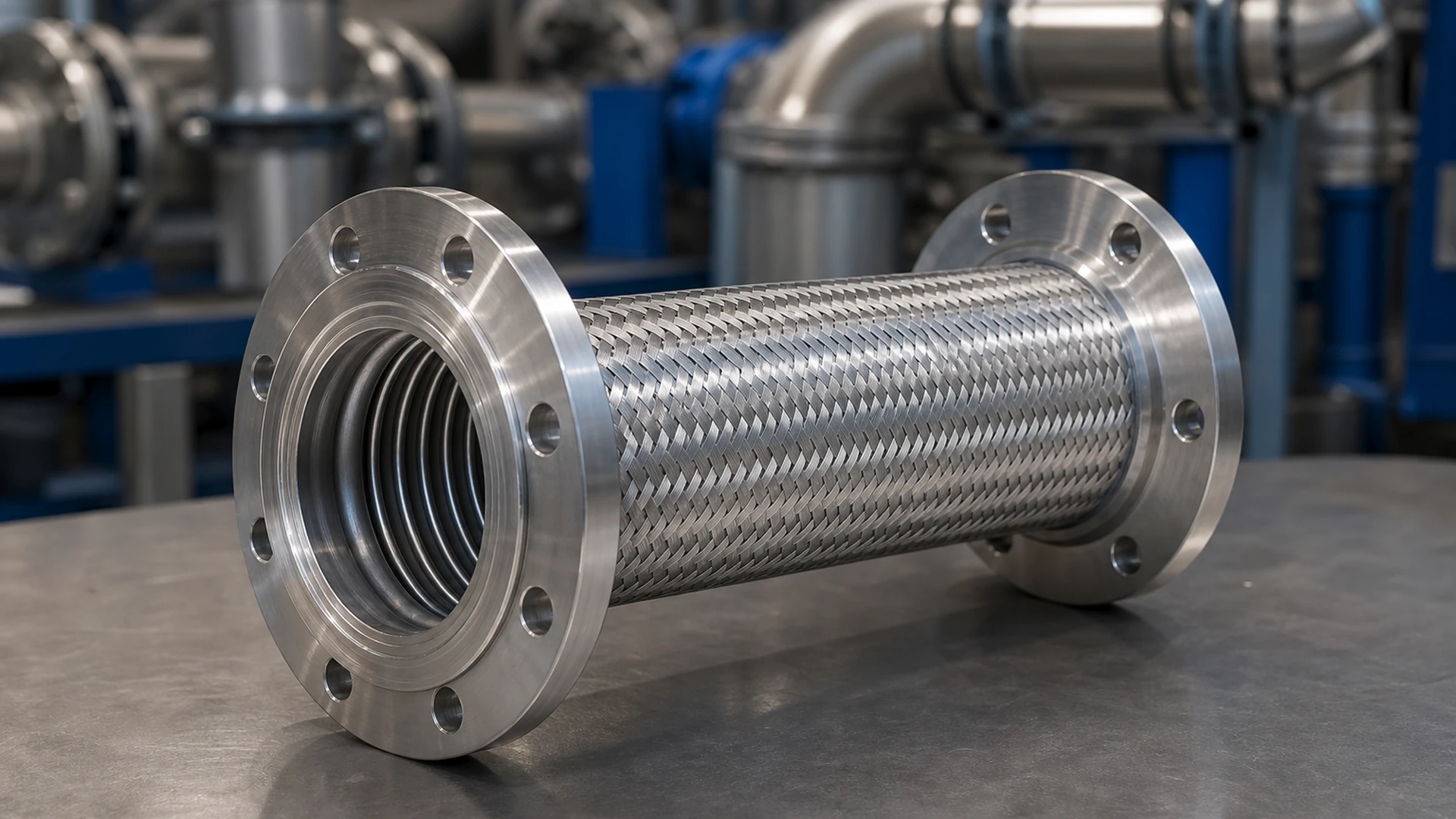 Application concept / illustrative visual
Assembly structure
Build the Specification From the Inside Out.
Corrugation, braid layers, stainless steel grade, weld method and end connections must be confirmed for the actual installation. Pending written factory confirmation.
Stainless steel braid material, wire construction and layer count: Pending written factory confirmation.
Collars, sleeves, reinforcement and external protection depend on the installation.
Welded or mechanically attached End A / End B construction: Pending written factory confirmation.
Family-specific buyer questions
Resolve the Questions That Change This Assembly.
Use these prompts to prepare the inquiry. They do not pre-confirm a construction or capability.
What corrugation or visible core profile is being replaced, and what dimensions can be measured?
What are the live length, overall length, installed offset and available bend space?
Is the movement direction axial, lateral, angular, vibration-driven or a combination?
Where are the collars, braid termination, weld zone and End A / End B interfaces located?
Approved product-family visual
Review the Visible Assembly Features.
Only matching product-series visuals from the latest owner-approved machine manifest are shown.
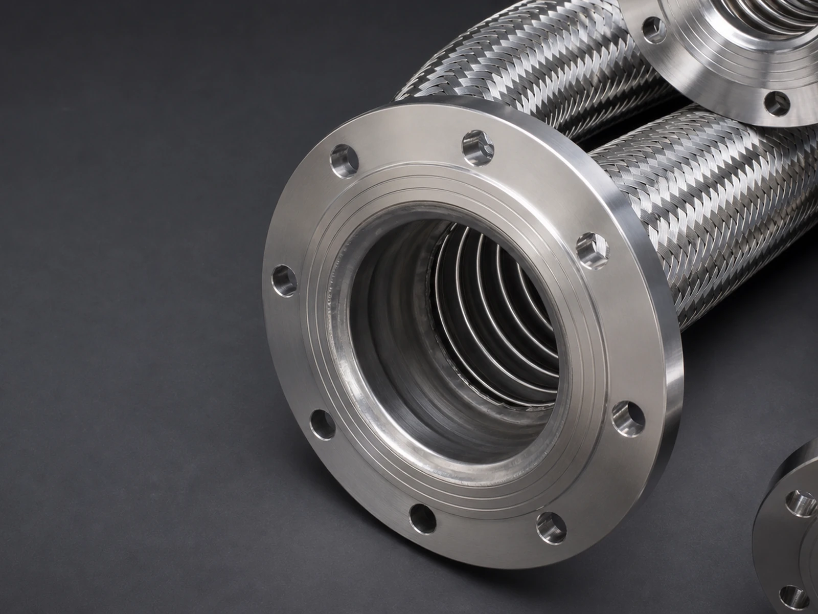 Application concept / illustrative visual
Design directions
Translate the Duty Into Four Review Questions.
These are selection directions, not published Aureko ratings.
High-pressure duty review — cycling and vacuum inputs
Record normal, peak, vacuum and pressure-cycle conditions for the complete corrugated assembly review.
High-temperature duty review — thermal movement inputs
Record fluid, ambient and nearby heat plus expected thermal movement at the installed geometry.
Corrosion and compatibility review — core and weld-zone inputs
Identify the medium, external exposure and required wetted materials without inferring a metal grade.
Abrasion or external-protection review — movement envelope
Show movement direction, contact points, handling risk and the space available to the assembly.
Applications
Use the Installation to Define the Assembly.
- Suitability is reviewed from the actual medium, duty, movement, interfaces and installation; an application name alone is not an approval.
- A visual, sample or previous part can support identification but cannot prove material, performance, compatibility or certification.
Review sequence
Move From Field Evidence to One Written Basis.
The sequence differs by product family because the uncertain interfaces differ.
- 01Draw the installed geometry
Record fixed points, offset, movement direction, available space and nearby heat or contact. - 02Separate live and overall length
Measure flexible live length, overall length, end lengths, angles and clocking. - 03Identify core, braid and ends
Use photos or a drawing to show corrugation, braid layers, collars, weld zones and both interfaces. - 04Approve one written assembly basis
Use the confirmed geometry, construction, joining, test and document scope as the quotation basis.
Custom options
Define End A, End B and the Hose Between Them.
Nominal DN/ID size, live length, overall length, offset and orientation.
Core material, braid layers, collars, guard and external protection.
End A and End B connection, material, sealing face, angle and clocking.
Quantity, drawing, marking, packing, test and document requirements.
RFQ checklist
Send These Inputs for a Useful Review.
Photos and drawings help identify interfaces. Written fields define the quote basis.
- 01Conveyed medium, concentration and cleaning method where applicable.
- 02Normal and peak pressure, vacuum or pulsation, plus minimum and maximum temperature.
- 03DN or inner diameter, usable length, overall length, tolerance and quantity.
- 04Movement condition, installation route, available space and external environment.
- 05End A and End B type, size, standard, sealing face, material and orientation.
- 06Required drawing, test method, acceptance record, marking, packing and documents.
Inquiry photo brief
Photograph the Interfaces That Words Miss.
- One full assembly photo beside a scale, showing live length and overall length.
- One installed photo showing fixed points, offset and movement direction.
- One close photo of each braid termination, collar and visible weld zone.
- One close photo of End A and End B sealing faces, orientation and markings.
Written confirmation boundary
Specific materials, pressure, temperature, compatibility, assembly method, tests, certifications and document availability remain Pending written factory confirmation for the order-specific construction.
Product FAQ
Clarify the Assembly Before Quotation.
Confirm the inner corrugated core construction, braid, medium, pressure cycling, temperatures, movement direction and installation geometry in writing.
Confirm End A and End B connection, material, thread or flange standard, sealing face, angle and clocking.
Confirm the drawing review, leak, pressure, weld or dimensional test criteria and required documents before quotation or production.